This guide covers configuring an SPI-connected framebuffer display (using the SH1106 OLED as an example) on a Buildroot image for the Raspberry Pi Zero 2W. It assumes you already have a working Buildroot image with SPI enabled — if not, start with Setting Up a Buildroot Linux Image on the Raspberry Pi Zero 2W first.
1. Kernel Configuration
Two kernel components are required:
spi-bcm2835— the SPI bus driver for the BCM2835/2837 SoCfb_sh1106(or the equivalent fbtft driver for your display) — the framebuffer driver
In make menuconfig, navigate to the kernel configuration and make sure both are set to <*> (built-in), not <M> (module).
<M>means the driver is compiled as a loadable module and must be brought up manually withmodprobeon each boot. Building them in as<*>means they are part of the kernel image and initialize automatically — which is what you want for a display that should be ready at boot.
2. Boot Configuration
In config.txt on the boot partition, add:
Adjust dc_pin and reset_pin to match your wiring.
Making This Persist Across Builds
Editing config.txt on the SD card directly works for one-off changes, but it gets overwritten on every flash. To make it permanent, edit the file in your Buildroot board directory instead:
Alternatively, add it to a post-build script so it gets applied automatically alongside other configuration tasks during the build process.
A Note on spidev
If spidev is needed alongside the display driver, make sure it is loaded after the display driver has initialized. If spidev claims the SPI bus first, the framebuffer driver won’t be able to attach to it — see the debugging section for how to detect and fix this.
3. Verifying the Setup
After booting, check dmesg for SPI-related output:
dmesg | grep -i spi
A successful setup looks like this:
The last line confirming a named frame buffer (graphics fb1) means the driver initialized and a framebuffer device was created. This is a good sign, but it doesn’t prove the display itself is working — wiring issues won’t show up here.
Functional Test
Push random data to the framebuffer device to confirm the display actually responds:
dd if=/dev/urandom of=/dev/fb1 bs=1024 count=16
If the display shows noise or any visual change, the driver, SPI bus, and wiring are all working. If nothing appears, the problem is hardware or wiring — see the debugging section below.
4. Debugging
Work through these steps in order. Each one rules out a specific failure mode.
Step 1 — Check if spidev Stole the Bus
ls /dev/spi*
If /dev/spidev0.0 exists, spidev has claimed the SPI bus before the framebuffer driver could attach. Remove it and reload the display driver:
rmmod spidev
modprobe fb_sh1106
If this fixes it, the long-term solution is to ensure spidev is not loaded at boot, or to load it only after the framebuffer driver is up.
Step 2 — Mount debugfs
debugfs is not mounted by default on Buildroot. Several of the following steps depend on it:
mount -t debugfs debugfs /sys/kernel/debug
Step 3 — Check GPIO Ownership
cat /sys/kernel/debug/gpio
Look for these entries:
| Entry | Meaning |
|---|---|
GPIO24 | dc | DC pin claimed by the driver ✓ |
GPIO25 | reset | RST pin claimed by the driver ✓ |
| GPIO 8, 10, 11 with no owner | SPI pins not muxed — problem |
If the SPI pins (8, 10, 11) have no owner, the SPI peripheral is not active. Continue to Step 4.
Step 4 — Check SPI Pin Mux
cat /sys/kernel/debug/pinctrl/3f200000.gpio-pinctrl-bcm2835/pinmux-pins | grep -E "pin 8|pin 10|pin 11"
Expected output:
If pin 8 shows MUX UNCLAIMED — you likely have spi0-0cs in config.txt. Remove it.
If pins 10 or 11 show MUX UNCLAIMED — dtparam=spi=on is not being applied. Verify it is present in config.txt and that the file is being read from the correct partition.
Step 5 — Verify the SPI Node Is Enabled in the Device Tree
strings /proc/device-tree/soc/spi@7e204000/status
This must print okay. If it prints disabled or nothing, the SPI peripheral was not enabled in the device tree — go back and confirm dtparam=spi=on is in config.txt.
Result
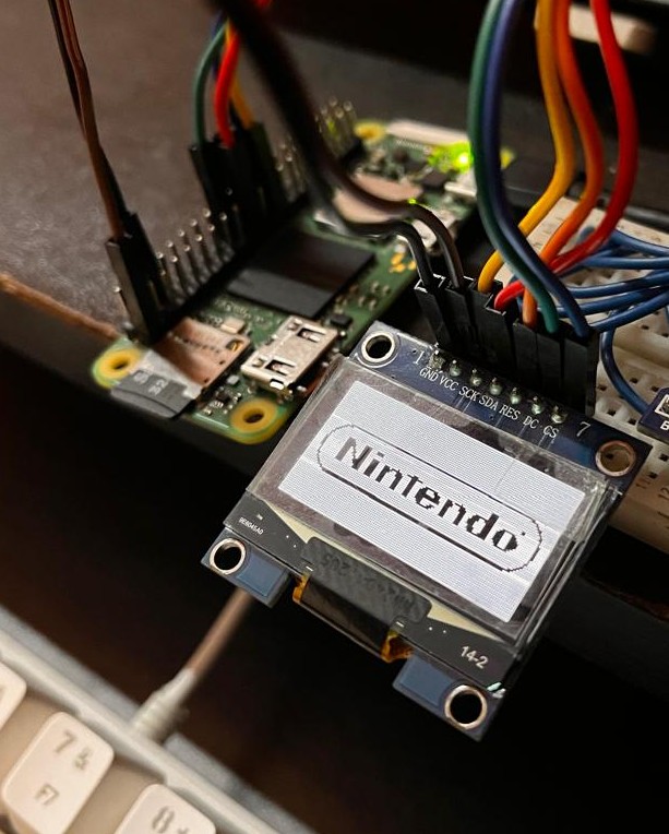
I loaded up a Nintendo logo on the screen.
Realizations
This is not really the best way to handle a monochrome display on a setup like this.
I played around with the debug commands and noticed that the display used RGB565 format. This was problematic because with each pixel being 16 bits and the display being 128×64, one has to use a 16 kB framebuffer. This is a waste, since ideally I would like to have something closer to a 1 kB buffer given that the display is inherently monochrome.
But as all of this is being handled internally by fbtft, there is no straightforward way I saw to change the framebuffer format or reduce the memory footprint to a 1-bit packed representation.
So, the solution is to just write my own SPI driver for handling the display over SPI. This would allow me to bypass the generic framebuffer abstraction entirely and directly manage a 1-bit buffer, packing pixels efficiently and pushing only the necessary data over SPI.
In practice, this should reduce memory usage significantly, simplify control over updates, and give much finer-grained control over how and when the display is refreshed.
I would probably be exploring this next.